


1. Characteristics of RF PCB connectors
The main function of an RF PCB connector is to establish a low-loss, high-fidelity signal channel between the PCB and external RF systems (such as antennas, test instruments, coaxial cables), while ensuring the integrity of high-frequency signals.
Compared to ordinary RF connectors, RF PCB connectors are specifically designed for high-frequency signal transmission, offering notable comprehensive advantages. These products come with a standard 50Ω configuration, ensuring seamless compatibility with the entire RF equipment. Equipped with high-quality conductors and insulating materials, they can effectively reduce signal transmission loss. Additionally, some RF PCB connectors feature a fully enclosed shielding structure, providing immunity to external electromagnetic interference and enabling them to easily handle various complex operating environments. Furthermore, they are flexible in installation, adaptable to multiple installation methods, resistant to high temperatures, and maintain stable electrical performance.
2. Application of RF PCB connectors

RF PCB connector, SMP SMT plug (limiting)
The impedance is 50 ohms and the maximum frequency is 40 GHz. This RF connector is designed for various printed circuit board applications in RF and microwave systems. The SMP connector utilizes beryllium copper contacts and gold-plated nickel on copper-plated materials.
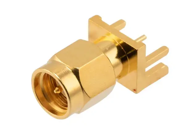
RF PCB connector, SMA, male thread, up to 6GHz, end launch, straight type, 0.062 inch PCB thickness
The impedance of the connector is 50 ohms. This RF connector features a terminal launch connector mounting interface, specifically designed for various printed circuit board applications in RF and microwave systems. It utilizes a PTFE dielectric type and boasts a voltage standing wave ratio of 1.07:1. The connector is resistant to both low and high temperatures.

RF PCB connector, SMA, female thread, up to 18GHz, surface mount, straight type, spacer
The impedance of the connector is 50 ohms, with a maximum frequency of 18 GHz and a voltage standing wave ratio of 1.15:1. The connector is resistant to both low and high temperatures.

RF PCB connector, MCX female straight-through, edge-mounted, end-emitting
The impedance of the connector is 50 ohms, with a maximum frequency of 6 GHz and a voltage standing wave ratio of 1.3:1. The connector utilizes beryllium copper contacts and gold-plated nickel on copper-plated materials.


